Les rayons X sont utilisés pour étudier les propriétés structurelles des solides, des liquides ou des gels. Les photons interagissent avec les électrons et fournissent des informations sur les fluctuations des densités électroniques dans la matière. Un montage expérimental typique est illustré à la figure 1 : un faisceau monochromatique de vecteur d’onde incident ki est sélectionné et tombe sur l’échantillon. L’intensité diffusée est recueillie en fonction de l’angle de diffusion 2θ. Les interactions élastiques sont caractérisées par des transferts d’énergie nuls, de sorte que le vecteur d’onde final kf est égal en module à ki. Le paramètre pertinent pour analyser l’interaction est le transfert de quantité de mouvement ou vecteur de diffusion q=ki-kf, défini par :


The scattered intensity I(q) is the Fourier Transform of g(r), the correlation function of the electronic density r(r), which corresponds to the probability to find a scatterer at position r in the sample if another scatterer is located at position 0 : elastic x-ray scattering experiments reveal the spatial correlations in the sample. Small angle scattering experiments are designed to measure I(q) at very small scattering vectors q»(4p/l)q, with 2q ranging from few micro-radians to a ten of radians, in order to investigate systems with characteristic sizes ranging from cristallographic distances (few Å) to colloidal sizes (up to few microns).
· Electronic contrast. The number of photons scattered by one sample is proportional to its total volume V and to its electronic contrast . In the simple case of a binary system for instance, like scattering objects of density r1 embedded in a solvent of density r2, the electronic contrast is Dr=r1-r2. The higher the contrast between particles and solvent, the greater the signal.
· Absolute intensity. The experimental intensity is usually fitted in order to determine the density r(r), the size, the shape and the internal structure of one elementary scatterer, as well as the structure and the interactions between scatterers. The determination of physical quantities, such as molecular weight, particle volume, specific surface or osmotic compressibility, is feasible only if I(q) is measured on absolute scale. As shown on figure 1, a part of the incident red beam is absorbed in the material. The number of photons scattered in the solid angle DW in the direction 2q have to be normalised with respect to the number of photons transmitted through the sample (green beam). This imply to control several parameters : the sample thickness e (cm) and transmission T, the incident flux of photons f0 (photons/s) and the solid angle of the experiment DW. The absolute intensity can then be measured in absolute units (cm-1).
What does « q-range » mean ?
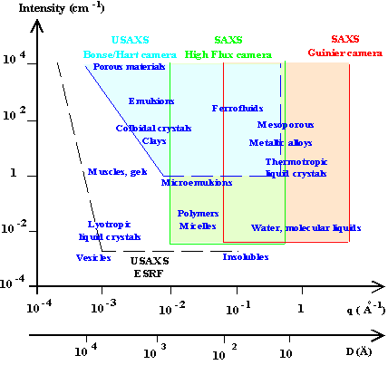
A typical small angle scattering intensity profile is shown on figure 2a. The intensity is plotted versus q, in the range qmin-qmax defined by the experimental set-up and usually fixed by geometric limitations
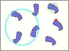
Intuitively, a measurement made at a given q0 allows to investigate the density fluctuations in the sample on a distance scale D0=2p/q0. It is equivalent to observe the system through a 2p/q0 diameter « window » in real space, as shown in figure 2b. The red circle is the observation window. A scattering signal is observed if the contrast Dr inside the circle is different from zero. To study objects much smaller or much larger than D0=2p/q0, another « window » has to be chosen. The smallest (largest) observation window is given by Dmin(max)=2p/qmax(min) : it determines the size of the smaller (bigger) particles that can be observed with the instrument.
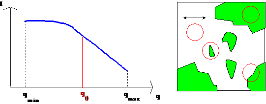
- left: Example of scattering intensity profile measured between qmin and qmax.
- Right: Binary sample and « q-window » corresponding to a measurement at a given q0.
High q domain :
The window is very small : there is a contrast only at the interface between the two media. This domain, called the Porod’s region, gives information about the surfaces.
Intermediary zone :
The window is of the order of the elementary bricks in the systems. The form factor P(q) can be measured (size, shape and internal structure of one particle).
Low q domain :
When the observation window is very large, the structural order can be obtained : it is the so-called structure factor S(q), which allows to calculate the interactions in the system.
Porod’s law : specific surface and interface
When two media are separated by a sharp interface, the scattered intensity follows an asymptotic law in the high q region : I(q)=Aq-4+B. This law is called the Porod’s limit (and is not verified any more for more complicated interfaces). The asymptotic value, when the electronic contrast of the sample is known, and when the intensity is expressed in absolute scale, allows to calculate the specific surface S of the particles.
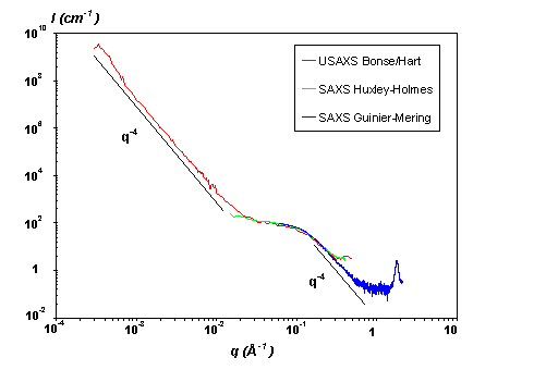
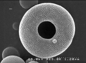
The q-range of validity of a Porod’s law can cover several decades, giving information about the particle sizes. When various types of particles, with different characteristic scales, exist in the sample, it is possible to measure different Porod’s law, as shown in the following example. Borosilicated glass are alterated and studied as a function of time, in order to investigate the alteration process. The initial glass before alteration can be represented as a two-media system, with large grains distributed in the solvent. The scattering signal shown in red is a Porod’s law resulting from the sharp interface between the solvent and the grain, ranging from 10-4 to 0.1 Å-1. When the sample is alterated a second Porod’s law appears at larger q : small pores are created in each grain. It is the sharp interface pore-grain that gives rise to that second law. As the pore’s size increases with time, the Porod’s law after 8 weeks is shifted to smaller q respect to the 2 weeks alteration glass signal. In this particular case, measuring the intensity on absolute scale is critical to calculate the pore’s surface (and radius, if a spherical shape is assumed), as well as the grain’s surface.
When two media are separated by a sharp interface, the scattered intensity follows an asymptotic law in the high q region : I(q)=Aq-4+B. This law is called the Porod’s limit (and is not verified any more for more complicated interfaces). The asymptotic value, when the electronic contrast of the sample is known, and when the intensity is expressed in absolute scale, allows to calculate the specific surface S of the particles.
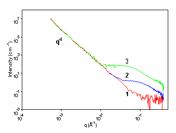
Figure 3 : USAXS on borosilicated glasses.
The q-range of validity of a Porod’s law can cover several decades, giving information about the particle sizes. When various types of particles, with different characteristic scales, exist in the sample, it is possible to measure different Porod’s law, as shown in the following example. Borosilicated glass are alterated and studied as a function of time, in order to investigate the alteration process. The initial glass before alteration can be represented as a two-media system, with large grains distributed in the solvent. The scattering signal shown in red is a Porod’s law resulting from the sharp interface between the solvent and the grain, ranging from 10-4 to 0.1 Å-1. When the sample is alterated a second Porod’s law appears at larger q : small pores are created in each grain. It is the sharp interface pore-grain that gives rise to that second law. As the pore’s size increases with time, the Porod’s law after 8 weeks is shifted to smaller q respect to the 2 weeks alteration glass signal. In this particular case, measuring the intensity on absolute scale is critical to calculate the pore’s surface (and radius, if a spherical shape is assumed), as well as the grain’s surface.
Form factor P(q) : size and shape of particles
Generally, the size and the shape of the particles is of fundamental interest to understand a material. X-ray small angle scattering gives valuable information, providing that the contrast is sufficient. If the particles are of the order of one micron, or larger, the results can be checked by light scattering. If the system is complex (three different media for instance), it can be completed by neutron scattering, which offers the possibility of contrast variation methods.
Experimentally, form factors can only be measured in the dilute regime where particles can be considered as independent scatterers without any interactions. In this case, the intensity is directly proportional to :
- the contrast Dr.
- the volume fraction f and the volume of one particle VP.
- the form factor of a single particle P(q).
· Elementary shapes. Form factors are easily calculated for spheres, cylinders, disks, rods, micelles, lamellas or Gaussian polymers, which are the basic shapes encountered in soft condensed matter. However, the only analytical expression is the sphere form factor that is represented on Figure 5.
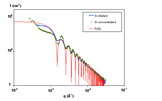
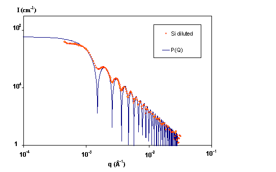
· Example. The experimental intensity scattered by a diluted solution of silica spheres of radius R=3000 Å is shown above on figure 4. The experiment has been performed on our laboratory Bonse/Hart camera. The data are compared to the theoretical form factor P(Q). Experimental data are smoothed compared to the model because of the instrument resolution (and some polydispersity). The location of the first minimum gives the radius of the particles : qR=4.5. A very good fit is obtained in this case with R=3000 Å. The extrapolation of the absolute intensity at q=0 allows to calculate the volume fraction of particles in the solvent.
Structure factor S(q) : interactions between particles
Complex systems are described through interaction potentials. Are the interactions attractive or repulsive, electrostatic or not ? is there any long range order in the system ? What is the effect of temperature, salt or pressure on the equilibrium ? SAXS experiments combined with adapted models bring some answers, provided the structure factor S(q) can be extracted from the scattered intensity I(q).
For instance, in the case of centrosymmetric identical particles in solution, the signal due to one single particle can be dissociated from the signal arising from the interactions between particles. The intensity is then proportionnal to the product P(q)*S(q).
