Interco is a low-noise analog/digital signal interconnection system reducing lab cabling complexity, with modular control and a Python command library.
Project Title: INTERCO
CEA Collaborators: LETS
External Collaborators: C2N
Funding: C2N
Start Date: 2022
Project Status: Five units currently in operation at C2N. Technology transfer in progress with Greenfield Technology.
Keywords: control, automation, measurement, electronics, your article…
Laboratory experiments often require measuring several physical quantities using various instruments (oscilloscopes, spectrum analyzers, lock-in amplifiers, etc.). The wiring of these signals can quickly become complex and cumbersome. Cable length and the various interconnection accessories can disturb the measurement, or even make it impossible. Moreover, repetitive wiring can cause errors that may lead to irreversible damage. INTERCO is a very-low-noise analog and digital signal interconnection system with a Python control library.
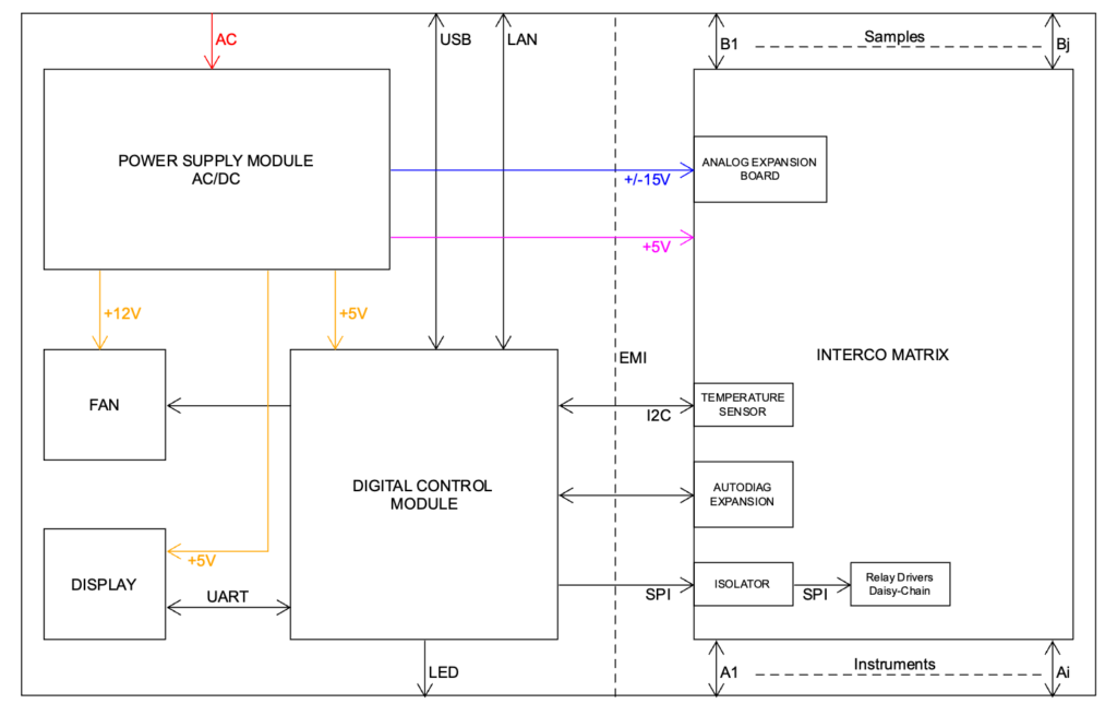
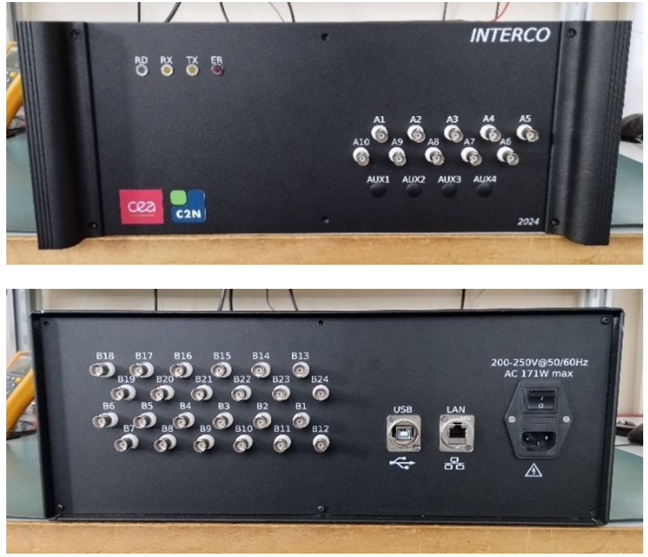
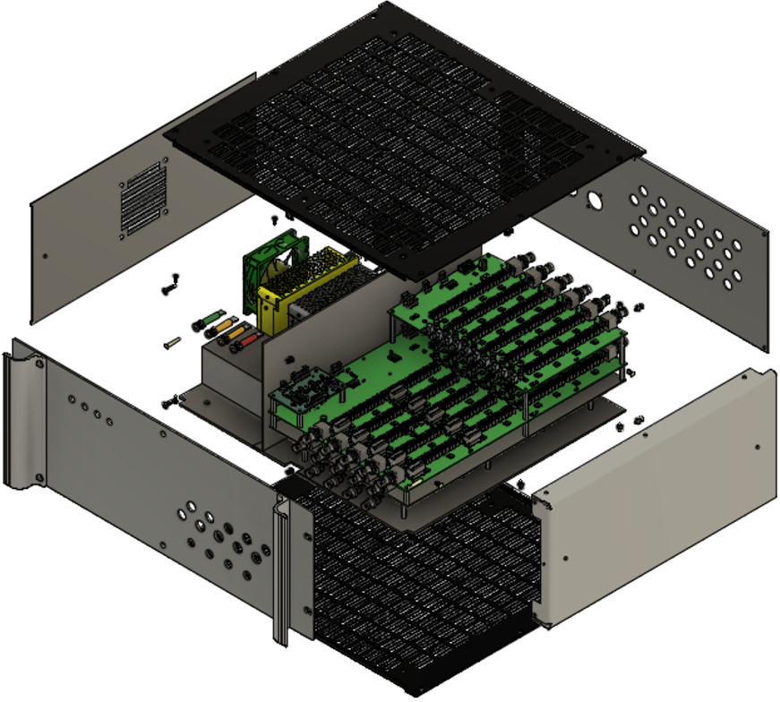
INTERCO is composed of several modules. The power-supply module converts the mains supply to provide the power and regulate the voltage levels required for system operation. Based on an STM32 microcontroller, the control module drives the system and offers an intuitive command interface. The interconnection matrix houses circuits based on electromechanical relays enabling bidirectional interconnection of signals on channels A and B. Channel A is intended for instruments and channel B for samples. Channel A also allows the integration of electronic boards to apply specific processing to the signal (e.g., filtering). In addition, the interconnection matrix includes temperature sensors to prevent temperature gradients by regulating the system temperature using a fan. The analog section containing the interconnection matrix is isolated from the rest of the system by conductive plates connected to ground.
INTERCO also integrates a self-diagnostic board to verify the proper condition of the interconnection lines. Indeed, relay contact resistance increases with use. By measuring this resistance variation, the system’s diagnostic board makes it possible to monitor wear of the interconnection lines.
Characteristics
Mains Supply
- RMS voltage (50–60 Hz): 210 / 230 / 250 V
- RMS current (50–60 Hz): 0.35 A
Signal
- Voltage (10 W max): 100 V
- Current (10 W max): 0.5 A
Bandwidth
- AiNF ↔ AjNF (AiNF & AiAj & AjAi & AjNF): 100 MHz
- AiNF ↔ Bj (AiNF & AiBj & BjAi): 50 MHz
Line Resistance (1)
- AiNF ↔ AjNF (AiNF & AiAj & AjAi & AjNF)
- Open line: 10¹² Ω
- Closed line: 0.9 – 1.5 Ω
- AiNF ↔ Bj (AiNF & AiBj & BjAi)
- Open line: 10¹² Ω
- Closed line: 1.3 – 1.7 Ω
Switching Time
- Relay opening time: 0.2 ms
- Relay closing time: 0.5 ms
Lifetime (2)
- Relay lifetime
- Resistive load 10 V, 10 mA: 10⁸ operations
- Maximum load: 10⁶ operations
Notes:
(1) Line resistance increases with use.
(2) Relay lifetime is specified for a maximum contact resistance of 1 Ω.