Dispositif d’aimant permanent cylindrique à champ magnétique induit d’orientation prédéterminée et procédé de fabrication
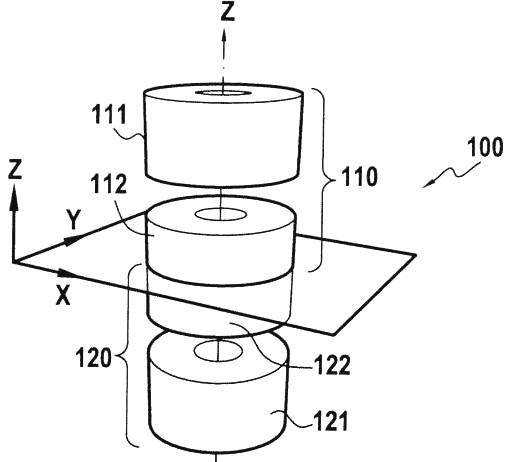
Le dispositif d’aimant permanent cylindrique induisant dans une zone d’intérêt centrale un champ magnétique homogène d’orientation prédéterminée par rapport à un axe longitudinal (z) du dispositif, comprend des première et deuxième structures aimantées annulaires (111, 121) disposées de façon symétrique par rapport à un plan (P) qui est perpendiculaire à l’axe longitudinal (z) et contient la zone d’intérêt centrale, et une troisième structure aimantée annulaire (112, 122) interposée entre les première et deuxième structures (111, 121) et également disposée de façon symétrique par rapport au plan (P) de symétrie. Les première, deuxième et troisième structures aimantées annulaires (111, 121, 112, 122) sont divisées en éléments constitutifs en forme de secteurs. La troisième structure aimantée annulaire (112, 122) est divisée en au moins deux tranches (112A, 112B, 122A, 122B) selon l’axe longitudinal (z) et tous les éléments constitutifs des première, deuxième et troisième structures aimantées annulaires (111, 121, 112, 122) sont aimantés selon une même direction de manière à créer dans la zone d’intérêt centrale un champ magnétique induit homogène et intense formant un angle prédéterminé par rapport à l’axe longitudinal (z). L’assemblage des pièces du dispositif peut avoir lieu avant l’aimantation de l’ensemble.
Cylindrical permanent magnet device with an induced magnetic field having a pre-determined orientation, and production method. (WIPO link)
The invention relates to a cylindrical permanent magnet device inducing a homogeneous magnetic field in a central zone of interest, said field having a pre-determined orientation in relation to a longitudinal axis (z) of the device. Said device comprises first and second annular magnetised structures (111, 121) arranged symmetrically in relation to a plane (P) that is perpendicular to the longitudinal axis (z) and contains the central zone of interest, and a third annular magnetised structure (112, 122) inserted between the first and second structures (111, 121) and also arranged symmetrically in relation to the plane (P) of symmetry. The first, second and third annular magnetised structures (111, 121, 112, 122) are divided into constitutive elements in the form of sectors. The third annular magnetised structure (112, 122) is divided into at least two sections (112A, 112B, 122A, 122B) along the longitudinal axis (z), and all of the constitutive elements of the first, second and third annular magnetised structures (111, 121, 112, 122) are magnetised in the same direction in such a way as to create, in the central zone of interest, a homogeneous and intense induced magnetic field, forming a pre-determined angle in relation to the longitudinal axis (z). The assembly of the parts of the device can take place before the whole set is magnetised.
Contact:: D Sakellariou


