


Brevets 2011
Numéro d'identification: WO/2013/087888 (lien OMPI)
Numéro d’identification CEA BD 13023
Année de dépôt : 15-12-2011
Date de publication : 20.06.2013
Système microfluidique 3d à zones emboîtées et réservoir intégré, son procédé de préparation et ses utilisations
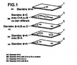
L’invention concerne un système microfluidique tridimensionnel (ou 3D) comprenant une pluralité de couches (1, 3, 5, 7, 9) empilées les unes sur les autres, caractérisé en ce qu'au moins une desdites couches est constituée d'une 1ère (3) et d'au moins une 2nde (10) parties, distinctes l'une de l'autre, avec la 2nde partie poreuse et mouillable par une solution d'intérêt s'emboîtant dans un évidement de la 1ère partie non poreuse et/ou non mouillable par ladite solution d'intérêt, ledit système pouvant éventuellement présenter un réservoir intégré; son procédé de fabrication et ses différentes utilisations
3d microfluidic system having nested areas and a built-in reservoir, method for the preparing same, and uses thereof (WIPO link)
The present invention relates to a three-dimensional (or 3D) microfluidic system including a plurality of layers (1, 3, 5, 7, 9) stacked on top of one another, characterized in that at least one of said layers consists of a first (3) and at least a second (10) portion which are separate from each other, wherein the second portion, which is porous and wettable by a solution of interest, is nested in a recess of the first portion, which is nonporous and/or non-wettable by said solution of interest, said system optionally comprising a built-in tank. The invention further relates to a method for manufacturing said system, and to the various uses thereof.
Contact T. Berthelot.
Numéro d’identification : WO 2013/005187 (lien OMPI)
Numéro d’identification CEA BD 12879
Année de publication 10-01-2013
Année de dépôt: 06-07-2011
Procédé de préparation de nanotubes de carbone contenant de l'azote et exempts de métal
La présente invention concerne un procédé de préparation de nanotubes de carbone contenant de l'azote (NCNT) et exempts de métal, ayant une structure cœur/écorce, dans laquelle le cœur est composé de carbone et l'écorce est principalement composée de carbone et d'azote. L'invention concerne également des nanotubes de carbone contenant de l'azote (NCNT) et exempts de métal, pouvant être obtenus au moyen dudit procédé, et leur utilisation comme catalyseur intervenant dans des réactions de réduction d'oxygène, notamment dans des milieux alcalins de piles à combustible.
Method for preparing metal-free nitrogen-containing carbon nanotubes (WIPO link)
The present invention relates to a method for preparing metal-free nitrogen-containing carbon nanotubes (NCNTs) having a core/shell structure, in which the core is composed of carbon and the shell is mainly composed of carbon and nitrogen. The invention also relates to metal-free nitrogen-containing carbon nanotubes (NCNTs) obtainable by said method and to their use as a catalyst for oxygen reduction reactions, notably in alkaline media in fuel cells.
Contact: B. Jousselme.

Numéro d’identification : WO 2011/023912 (lien OMPI)
Numéro d’identification CEA : BD
Année de dépôt : 28.08.2009
Année de publication : 03.03.2011
Assemblage de structures aimantées coaxiales induisant en son centre un champ homogène longitudinal
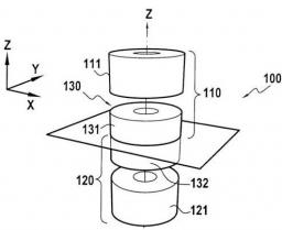
La structure aimantée induisant dans une zone d'intérêt centrale un champ magnétique homogène orienté selon un axe longitudinal (z) de la structure, comprend deux couronnes aimantées (111, 121) disposées de façon symétrique par rapport à un plan (P) perpendiculaire à l'axe longitudinal (z) définissant la zone d'intérêt centrale. Une structure aimantée annulaire médiane (330) est interposée entre ces deux couronnes aimantées (111, 121) et est disposée de façon symétrique par rapport au plan (P). La première couronne (111) est aimantée radialement par rapport à l'axe longitudinal (z) avec une aimantation divergente, la deuxième couronne (121) est aimantée radialement par rapport à l'axe longitudinal (z) avec une aimantation convergente, et la structure annulaire médiane (330) est aimantée selon l'axe longitudinal (z). La structure aimantée annulaire médiane (330) est divisée en deux tranches (331A, 331B, 332A, 332B) selon l'axe longitudinal (z) et les première et deuxième couronnes aimantées (111, 121), ainsi que les diverses tranches (331A, 331B, 332A, 332B) de la structure aimantée annulaire médiane (330), sont divisées chacune en éléments constitutifs en forme de secteurs régulièrement répartis.
Assembly of magnetised coaxial structures inducing a longitudinal homogeneous field in the centre thereof. (WIPO link)
The invention relates to a magnetised structure inducing, in a central zone of interest, a homogeneous magnetic field oriented along a longitudinal axis (z) of the structure, said structure comprising first and second magnetised crowns (111, 121) arranged symmetrically in relation to a plane (P) perpendicular to the longitudinal axis (z) and containing the central zone of interest, and a median annular magnetised structure (330) inserted between the first and second magnetised crowns (111, 121) and also arranged symmetrically in relation to the plane (P) of symmetry. The first magnetised crown (111) is radially magnetised in relation to the longitudinal axis (Z) with a divergent magnetisation, the second magnetised crown (121) is radially magnetised in relation to the longitudinal axis (z) with a convergent magnetisation, and the median annular magnetised structure (330) is magnetised along the longitudinal axis (z). The median (330) annular magnetised structure is divided into at least two sections (331A, 331B, 332A, 332B) along the longitudinal axis (z), and the first and second magnetised crowns (111, 121) and the various sections (331A, 331B, 332A, 332B) of the median annular magnetised structure (330) are each divided into constitutive elements in the form of regularly distributed sectors.
Contact: D. Sakellariou
Numéro d'identification : WO 2010/004225 (Lien OMPI)
Numéro d'identification CEA : BD
Année de dépôt : 11.07.2008
Année de publication : 14.01.2010
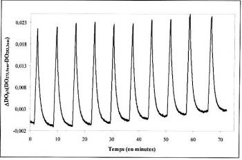
Détecteurs nanoporeux de composés aromatiques monocycliques et autres polluants
Matériau sol-gel poreux essentiellement constitué d'unités d'un ou plusieurs premier(s) polyalcoxysilane(s) choisi(s) parmi les composés suivants : le (chlorométhyl)triéthoxysilane; le 1,3- diméthyltetraméthoxydisiloxane; l'éthyltriméthoxysilane; le triéthoxy(éthyl)silane; le triéthoxyméthylsilane; le triéthoxy(vinyl)silane; le triméthoxyméthylsilane; le triméthoxy(vinyl)silane; le tétraéthoxysilane ou le tétraméthoxysilane (TMOS) et d'unités d'un ou plusieurs second(s) polyalcoxysilane(s) choisi(s) parmi les composés suivants: le (N-(3-(triméthoxysilyl)propyl)éthylènediamine; le 3- aminopropyltriéthoxysilane (APTES) et le 3-aminopropyltriméthoxysilane, dans un rapport molaire premier(s) polyalcoxysilane(s)/ second(s) polyalcoxysilane(s) de 1 /0,01 à 1 /1, comprenant éventuellement une molécule sonde, procédé de préparation et applications dans le piégeage d'hydrocarbures aromatiques monocycliques ainsi que d'autres polluants ou dans leur détection
Nanoporous detectors of monocyclic aromatic compounds and other pollutants (WIPO link)
Porous sol-gel material essentially consisting of units of one or more first polyalkoxysilanes chosen from the following compounds: (chloromethyl)triethoxysilane; 1,3-dimethyltetramethoxydisiloxane; ethyltrimethoxysilane; triethoxy(ethyl)silane; triethoxymethylsilane; triethoxy(vinyl)silane; trimethoxymethylsilane; trimethoxy(vinyl)silane; tetraethoxysilane or tetramethoxysilane (TMOS) and of units of one or more second polyalkoxysilanes chosen from the following compounds: (N‑(3-(trimethoxysilyl) propyl)-ethylenediamine; 3‑aminopropyl-triethoxysilane (APTES) and 3-aminopropyl-trimethoxysilane, in a first polyalkoxysilane/second polyalkoxysilane molar ratio of 1/0.01 to 1/1, optionally comprising a probe molecule, method of preparation and applications in the trapping of monocyclic aromatic hydrocarbons and other pollutants or in their detection.
Contact: T.H. Tran-thi.
Numéro d’identification : WO/2011/117407 (lien WIPO)
Numéro d’identification CEA BD 11723
Année de dépôt : 26-03-2010
Date de publication : 29-03-2011
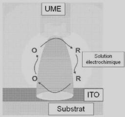
Procédé pour graver une couche d'oxyde métallique conducteur utilisant une microélectrode
L'invention concerne un procédé pour graver une zone sélectionnée d'une couche d'oxyde métallique conducteur déposée sur un support, consistant à éliminer ladite zone par voie électrochimique en présence d'une microélectrode polarisée et d'une solution électrochimique. La présente invention concerne également la couche gravée obtenue par un tel procédé.
Method for etching conductive metal oxide layer using microelectrode
(WIPO link)
The invention relates to a method for etching a selected area of a conductive metal oxide layer deposited onto a substrate, said method involving the electrochemical removal of said area in the presence of a polarized microelectrode and an electrochemical solution. The present invention also relates to the etched layer that is achieved by such a method.
Numéro d’identification : WO/2011/117407 (lien WIPO)
Numéro d’identification CEA BD 11723
Année de dépôt : 26-03-2010
Date de publication : 29-03-2011
Procédé pour graver une couche d'oxyde métallique conducteur utilisant une microélectrode
L'invention concerne un procédé pour graver une zone sélectionnée d'une couche d'oxyde métallique conducteur déposée sur un support, consistant à éliminer ladite zone par voie électrochimique en présence d'une microélectrode polarisée et d'une solution électrochimique. La présente invention concerne également la couche gravée obtenue par un tel procédé.
Method for etching conductive metal oxide layer using microelectrode
(WIPO link)
The invention relates to a method for etching a selected area of a conductive metal oxide layer deposited onto a substrate, said method involving the electrochemical removal of said area in the presence of a polarized microelectrode and an electrochemical solution. The present invention also relates to the etched layer that is achieved by such a method.
Numéro d’identification : WO/2010/112610 (Lien OMPI)
Numéro d’identification CEA BD 11094
Année de dépôt : 02.04.2009
Date de publication : 07.10.2010
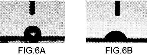
Procédé pour modifier l'énergie de surface d'un solide
La présente invention concerne un procédé et un kit pour modifier l'énergie de surface de la surface d'un solide. Le procédé comprend une étape de greffage sur ladite surface d'un film organique polymère constitué de polymères greffés, chaque polymère présentant un premier motif directement lié à ladite surface issu d'un sel d'aryle clivable et au moins un autre motif de la chaîne polymérique issu d'un élément choisi dans le groupe constitué par un sel d'aryle clivable fluoré, un (méth)acrylate fluoré et un siloxane à terminaisons vinyliques.
Method for modifying the surface energy of a solid
(WIPO link)
The present invention relates to a method and to a kit for modifying the surface energy of at least one surface of a solid, including a step consisting of grafting an organic polymer film consisting of graft polymers onto said surface, each polymer having a first unit directly bonded to said surface, derived from a cleavable aryl salt, and at least one other unit of the polymer chain, derived from an element selected from the group consisting of a fluorinated cleavable aryl salt, a fluorinated (meth)acrylate and a vinyl-terminated siloxane.
Contact: G. Deniau.