


Principle scheme
Internal conversion frequency imaging interferometer at 32nm
Interferometry allows for getting electronic density information in 2D. For this purpose, we have set up, in collaboration with Attophysic group and LCF-IO, an innovative instrument based on the mutual coherence properties of two High order Harmonic (HHG) from gas jet in the XUV domain. Interferometry, in this wavelength domain, exhibits strong difficulties, due to handling of the beams.
To overcome part of these problems, we have proposed a novating scheme in which a significant part of the optics is in the IR domain. The principle of the interferometer is reported on the following figure.
After a beam splitter, the IR beam is focused in two argon gas jets. The two XUV sources generated by frequency conversion in two spatially separated gas jets are the two arms of the interferometer. One is called the "reference" arm and the other, on which there is the object to characterise, is called the "probe" arm. The two XUV beams are recombined by a prism, following a triangular geometry. They are reflected by a plan mirror up to an ellipsoidal mirror. A multilayer, for selecting H25 (λ=32nm) has been coated on this optic, very delicate to manufacture. In addition to the spectral selection, the ellipsoidal mirror images the "virtual" object plane in the "real" image plane with a magnification of 10. A second mirror, coated with the same multilayer, increases the rejection of H23 and H27, and folds the XUV beams towards the detection system made of MicroChannel Plates (MCP) coupled to a phosphor screen.
This instrument exploits some of the intrinsic properties of HHG sources as the brightness, the short duration and the mutual coherence properties. Spatial resolution is 5µm in the object plane. The triangular geometry allows for probing objects of several 100's of µm2, related to the size of interferometric field.
A typical interferogram is reported bellow. It has been recorded at 32nm and the fringe spacing has been fixed to 12µm. The maximum contrast is of the order of 30%.
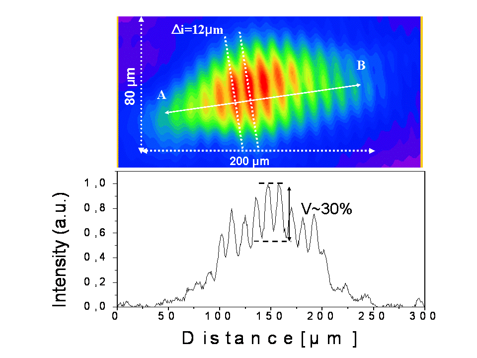
Up: interferogram at 32nm; down: intensity profile along AB
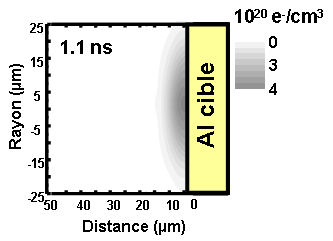
Electronic density map of the Al plasma at Δt=1.1ns
The instrument has been set up on the LUCA laser facility (CEA-Saclay - lien vers SLIC) and tested to determine the electronic density of an aluminium plasma. The target, located on the "probe arm", in the object plane of the interferometer (10cm away from the gas jet), has been irradiated by IR laser pulse focused at maximum intensity of 3x10¹⁶W/cm2. A delay line between IR pump beam and the XUV beams is used to study the temporal evolution of the plasma.
On the following figure, a 2D density map is presented, extracted from an interferogram recorded 1.1ns after the creation of the plasma. The maximum electronic density is 3x1020cm-3.
We validate the basic concept of the instrument by demonstrating the mutual coherence of the two XUV beams generated in two gas jets separated by a large distance (20cm). Interferograms at 32nm are routinely obtained at 20Hz repetition rate using 50fs IR beam with only 2-4mJ energy. The interference field is close to 100x200µm2 in the object pane and the maximum contrast of the interferograms is 30%. Its ultimate spatial resolution is 5µm, whereas the time resolution given by the XUV pulse duration is of a few 10fs. The typical triangular geometry of the interferometer offers the possibility to accommodate large size object under study. The ensemble is very compact and could be carried on other laser facilities.
S. Dobosz et al., RSI (2009) 80, 113102
• Service des Photons Atomes et Molécules • Service des Photons Atomes et Molécules
• Laboratoire Francis Perrin • pas de titre • Matter under Extreme Conditions • Groupe édifices nanométriques • Laboratoire Francis Perrin • Matière sous conditions extrêmes • Support et Lasers à Impulsions courtes / Support and short pulse lasers
