
| by Vadim S. Nikolayev | |
|
One of the contemporary technological challenges is a reduction of mass of various devices in order to reduce their energy consumption and CO2 emission. This requires replacing of metals by lighter synthetic materials (composites, ceramics, etc.), which, however, are poor heat conductors and thus require special thermal management solutions for their cooling capability to handle heat loads up to several kW. On the other hand, with the increase of power levels related to the miniaturization of electronics progressing towards multi chip modules, conventional cooling technologies and thermal management are facing growing challenges including the cooling heat fluxes of 100 W/cm2, long term reliability, and very low costs for consumer market products, among others. This necessitates the development and use of more efficient, nontraditional cooling approaches. Special devices called heat pipes are used more and more widely to transfer the excessive heat to a colder environment. For instance, now they are present inside each smartphone for the processor cooling.
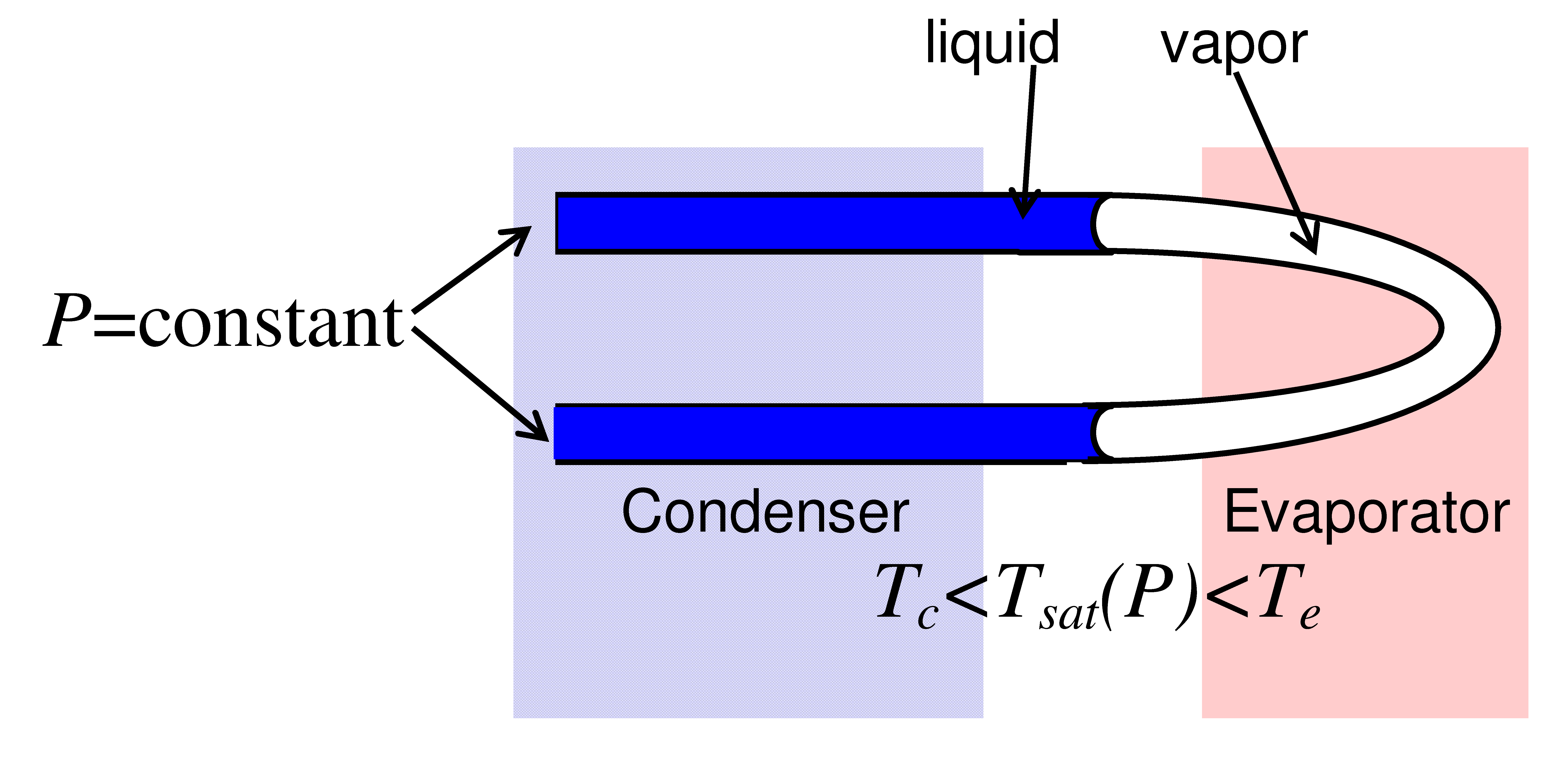
A heat pipe is a closed container tube filled with the working, usually pure fluid. One end of the container (forming evaporator section of the tube) is brought in thermal contact with a hot point to be cooled. The other end (called condenser section) is connected to the cold point where the heat can be dissipated. The tube portion between evaporator and condenser is called adiabatic section.
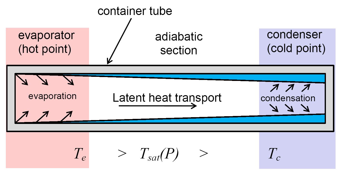
The working fluid, its mass and pressure are chosen in such a way that the saturation temperature is between the evaporator temperature Te and condenser temperature Tc. The fluid is thus vaporized in the evaporator section. The created vapor is transported to the condenser section by expansion and condenses there. The liquid is transported back to the evaporator section. The heat is transferred mainly due to the latent heat absorption in the evaporator and its release in the condenser. Since the latent heat is large, the heat pipes are quite efficient. They are capable of evacuating up to 100-200 W/cm2. There are several kinds of heat pipes. They differ by their geometry and a mechanism of liquid phase transport. In capillary heat pipes widely are most common as they are widely used in the smartphones and computers. The liquid is transported inside them thanks to a porous wick that provides the capillary suction. Another commonly used heat pipe kind is the thermosyphon where the liquid transport is provided by gravity. Evidently, they are much larger but capable of cooling of much more powerful devices. Unlike capillary heat pipes, they cannot be turned upside down or used in weightlessness.
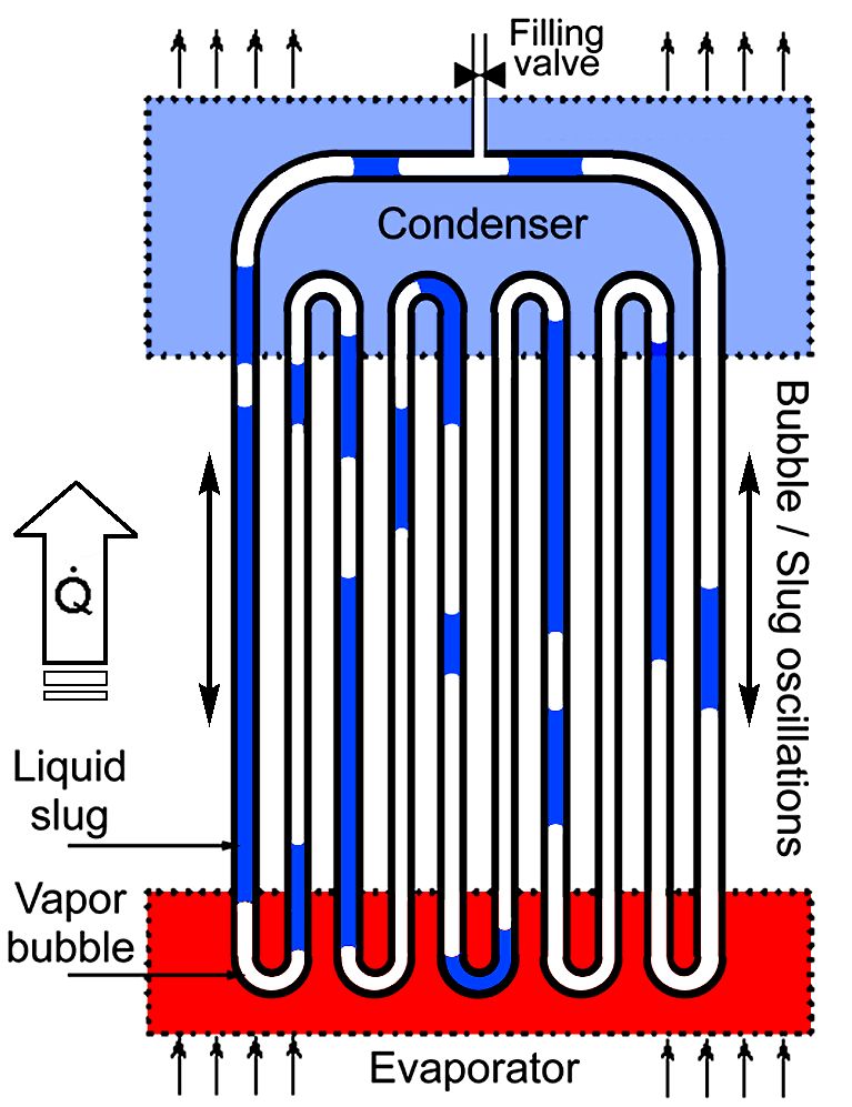
Pulsating (or oscillating) heat pipe, invented in early 1990s present promising alternatives for the removal of high localized heat fluxes. At the same time, their mechanism of functioning is gravity-independent. PHP is a capillary tube (with no wick structure) bent into many turns and partially filled with a working liquid. Because the tube is thin, the liquid plugs and vapor bubbles are formed inside it.
|
|
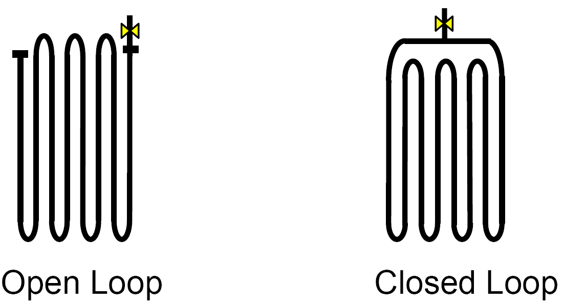 |
| Two possible PHP topologies. |
When the temperature difference between evaporator and condenser exceeds a certain threshold, the gas bubbles and liquid plugs begin to oscillate spontaneously back and forth. The amplitude of oscillations is quite strong and the liquid plugs penetrate into both condenser and evaporator. The heat is thus transferred not only by the latent heat transfer like in other types of heat pipes, but also by sweeping of the hot walls by the colder moving fluid and vice versa. This phenomenon is the reason of high efficiency of PHPs in comparison with other types of heat pipes. Compared to other cooling solutions, PHPs are simple and thus more reliable and cheap. They are capable to transfer several kW to distances of the order of 1 m even when their orientation with respect to gravity is unfavorable. For comparison, advanced heat pipes used for spatial applications have heat transfer capacity (measured in W·m) order of value smaller. The heat transfer capacity of the conventional heat pipes used for cooling of microelectronic devices like laptop computers is 2 to 3 orders of value smaller than that of PHPs. These features make PHP extremely promising for the thermal management of the next generation of electronic and other systems. However, the functioning of PHPs is not completely understood. A complicated interplay of different hydrodynamic and phase-exchange phenomena needs to be accounted for in the modeling approaches. Unlike other heat transfer devices, the functioning of PHPs is non-stationary and thus difficult to model. A large number of PHP-related studies have been carried out since 1990s, both experimental and theoretical. Researchers agree that the oscillations are driven by an instability that appears due to coupling of the adiabatic vapor compression and evaporation/condensation mass exchange. However this instability has not been studied until recently. Such important parameters as oscillation threshold, heat transfer coefficient, and maximum heat load cannot yet be predicted reliably from calculations. In most cases, the PHP parameters are adjusted empirically. However their industrial development has been initiated by several companies like Thermavant, Peregrine, ACT, Argotec, or Novark.
There are two possible PHP geometries: open loop and closed loop PHP. In the open loop PHP, the ends may be open or closed. Generally, the closed loop PHP is more efficient. For this reason, we target this type of the PHP in our numerical multibubble modeling presented below.
The oscillations appear as a result of an instability: small perturbation of an equilibrium state leads to the increasing in time oscillations until their amplitude is stabilized by the energy dissipation. Most researchers agree that he instability appears due to coupling of the adiabatic vapor compression and evaporation/condensation mass exchange. When a meniscus penetrates into evaporator, the vapor is produced, its pressure grows and pushes the meniscus back to the condenser. When the meniscus penetrates into condenser, the vapor pressure drops because of condensation which leads to the inversion of the meniscus motion. The liquid plug inertia produces a phase shift between the pressure and meniscus position variations, which is needed for the instability appearance. Yet this instability is not well understood. What is the critically unstable mode in the system? What provides the instability threshold? What defines the oscillation frequency? Is the oscillation stopping threshold (measured by lowering the heating/cooling power) differs from the oscillation start threshold? These questions need to be answered. We proposed a simple film evaporation-condensation (FEC) model that describes the simplest PHP that contains one bubble and one liquid plug. We have discussed the factors that define its frequency and the threshold of oscillations. The model shows the importance of the liquid films left on the internal wall of the tube by the receding liquid plugs. The model agrees with the experimental results obtained in collaboration with CETHIL. More information on modeling can be found in a comprehensive review article.
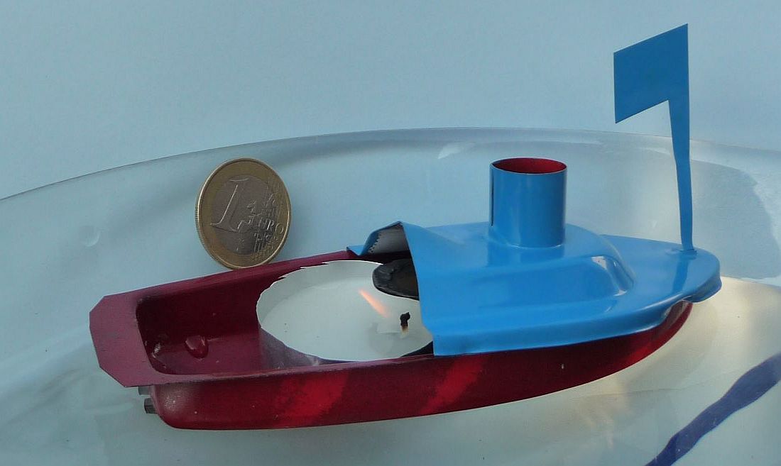
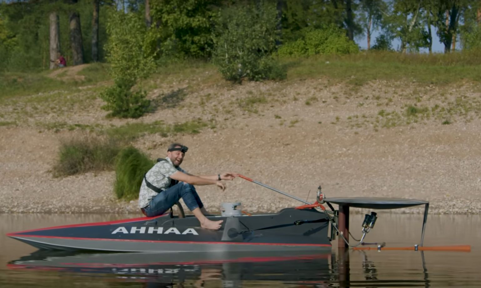
There is a children's toy that is called “pop-pop” steam boat (called by some “click-click” or “putt-putt” boat). Its name comes from the sound made by this toy while it moves. The sound is made by the cover of the fluid tank made of the thin metal membrane. The latter deforms when the pressure inside the tank varies and makes the sound. Web sites in English and in both English and French present interesting features of the pop-pop boat and how to do it yourself (the toy is sold in traditional toy shops in France, you can also find it in major online shops like Amazon). The steam boat was highly popularized thanks to the animated movie for children “Ponyo” produced by Studio Ghibli in 2008. The director is Oscar Award winner Hayao Miyazaki. Here is the 2 min multi-language clip of “Ponyo” where the characters prepare the pop-pop boat for their adventure. There are enthusiasts who even produced the pop-pop-boat of human size (spoiler: boat moved but veeery slow).
 |
 |
 |
 |
|
| Pop-pop boat | Sosuke's Boat (Ponyo animated movie, Studio Ghibli, 2008, under direction of Hayao Miyazaki) | Scheme of the pop-pop boat | Video of the pop-pop boat | Human size pop-pop boat. Screen capture from this video |
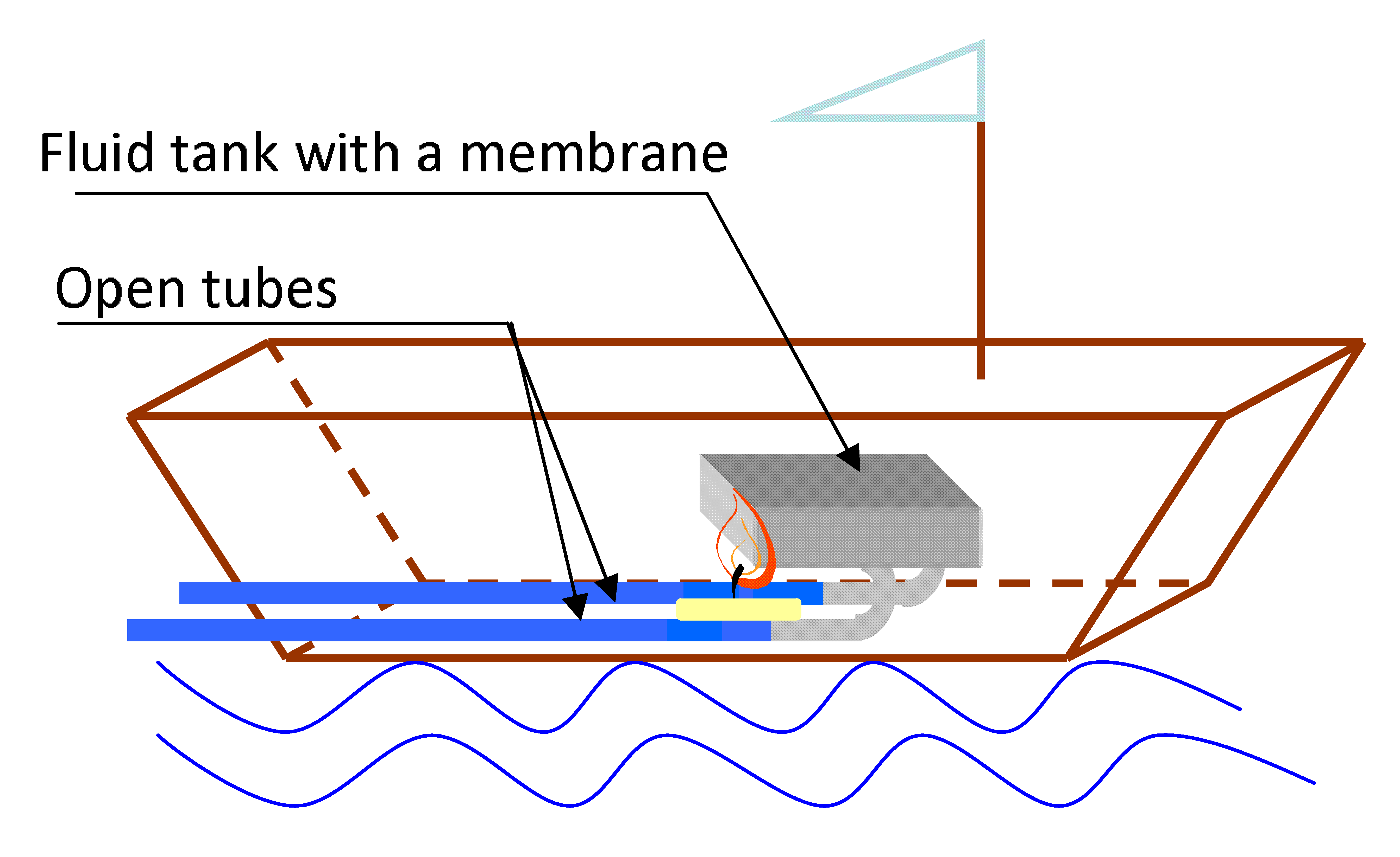
The boat engine is similar to the PHP. The immersed tube part plays the role of condenser. The water reservoir (tank) works as evaporator.
 |
| Scheme of the engine of the pop-pop boat |
This boat works according to the same principle as the PHP. The water plugs oscillate inside the open tubes and the water is alternatively expelled or sucked up. During the expulsion, the water flow is directed backwards while the suction is nearly isotropic. The created differential momentum (see Appendix A of the linked file) propels the boat forward.
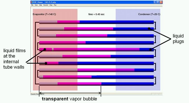
As explained above, because of the complexity of the PHP functioning, it is difficult to develop general recommendations concerning the PHP design. Perhaps the only one reliable recommendation concerns the tube diameter that should be small enough so the tube is a capillary and the liquid can form plugs inside. For this reason, the only way to predict the PHP functioning is its numerical simulation. We developed a software called CASCO, which is an abbreviation of its French title (Code Avancé de Simulation de Caloduc Oscillant meaning Advanced PHP Simulation Code). In the CASCO version 3.0, the model of each bubble-plug pair is based on the FEC single bubble model. It is capable to describe the variable bubble number so that events like bubble coalescence or bubble generation by boiling. In the next CASCO version, a more advanced film model will be used. It is based on the detailed fluid dynamics studies of the film behavior during oscillations. The C++ computer code of CASCO is object oriented (one finds the details in the article of Nikolayev (2011) and in a more recent article of Abela et al. (2022)). The data are input via a text file. One needs to specify there the PHP geometry, the structural material parameters, thermal boundary conditions and the initial conditions. The fluid parameters (except of saturation pressure and viscosity that vary strongly with temperature) have to be specified there too in the present version 3.0 (an interface with NIST REFPROP® fluid database is foreseen in the next version to get the data automatically). At the end of execution, CASCO generates an output data file <input file name>.php. Its size depends on the number of time records chosen to be saved by the user and can be quite large. The output is thus difficult to process manually. Several data postprocessing applications are developed. Most of them serve to extract and visualize one or the other parameter. A specific postprocessing application, called PHP_Viewer, has been developed. It allows visualization of the dynamics of gas-liquid interfaces and of the wetting (liquid) films that envelope the gas. The film dynamics is very important because their evaporation/condensation is the main moving force of the oscillations. The wetting films cover the internal tube walls completely when the gas exists in the condenser and adiabatic sections. In each evaporator section, one or several dry spots can be formed because of the film partial vaporization. The film length in the evaporator changes. The films are deposited on the walls by the receding gas-liquid menisci or “swallowed” when they advance. One can turn on the visualization of the temperature distribution inside the liquid and along the tube walls. The current simulated time moment and the temperature scale are both presented on the top. The next figure shows how the liquid plugs, the vapor and the films are represented by PHP_Viewer. The evaporator area is shown with light red and the condenser with light blue color.
An example of the PHP modeling (the working fluid: water) is presented on the video. It shows also some functionality of PHP Viewer v.1.5 like animation speed control.
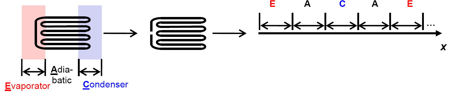
To optimize the code performance, the CASCO approach is one dimensional. The only space variable x follows the PHP tube meander. The modeling is performed by breaking the loop, “unbending” it, and imposing periodic boundary conditions at its ends as is shown in the figure below. The evaporator, adiabatic and condenser sections are indicated there with the same colors as above and with the letters E,A,C, respectively.
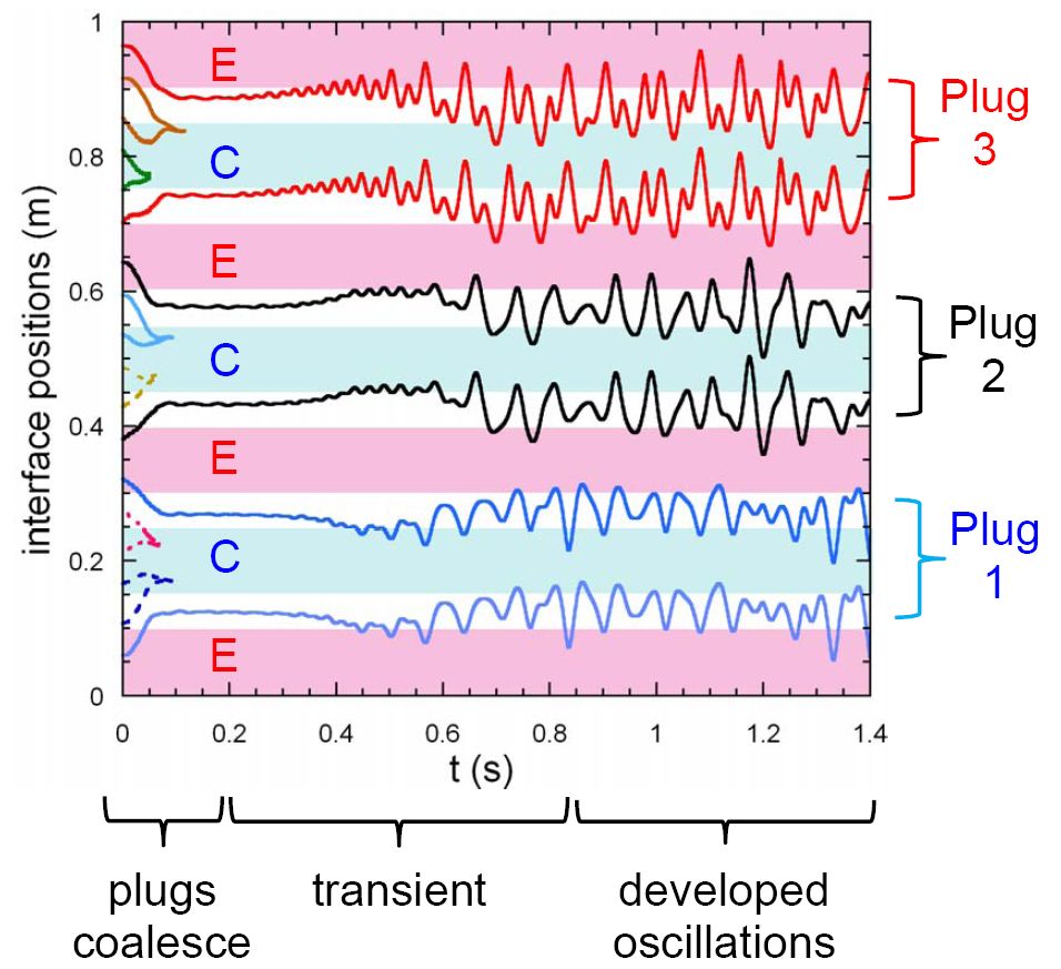
The time evolution of positions of the gas-liquid interfaces is plotted below. Only a part of the whole x extension is shown. Several stages of the evolution can be distinguished. First, some bubbles disappear because the liquid plugs coalesce between them. The coalescence corresponds to the point where two interfaces meet each other. The instability develops next and the amplitude of oscillations grow with time. The last stage is that of the developed oscillations.
The PHP_Viewer can display the liquid temperature distribution shown by colors. The correspondence colors-temperatures are shown with a bar at the top of the screen. Red (blue) corresponds to the highest (lowest) displayed temperature. An example of the temperature variation in the liquid is presented in the video below where the gravity is directed to the right. It shows that the ends of the liquid plugs that enter the evaporator become warmer than the rest of the plugs. The temperature of the liquid-vapor interfaces is the saturation temperature that may quickly vary in time (following the pressure of the vapor). An example of the temperature variation in the regime of developed oscillations is shown in the video below.
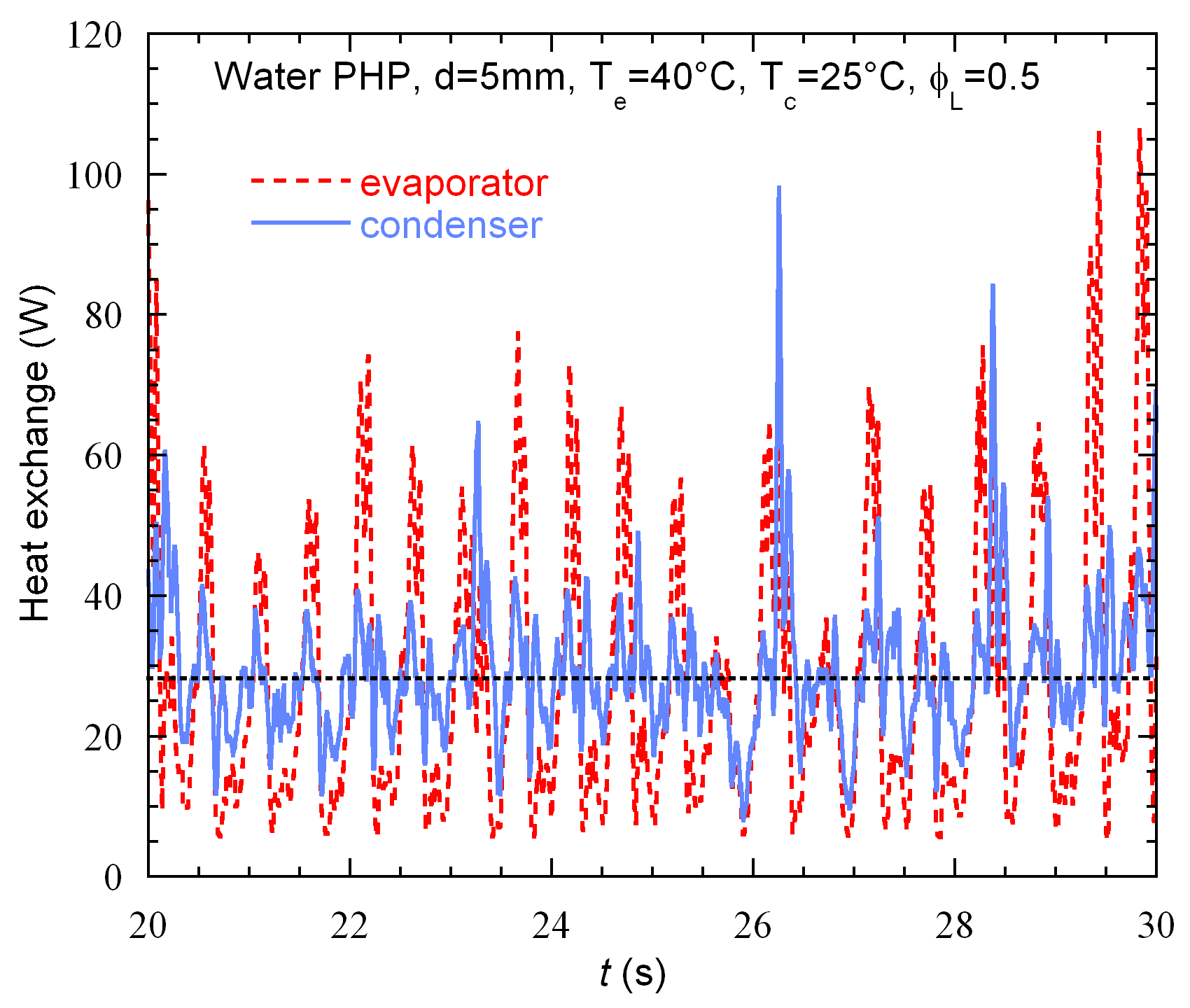
The corresponding heat transfer evolution is shown in the image below. The heat exchange with evaporator and condenser are shown. In the developed regime, a dynamic equilibrium is established: the time average of the power taken from evaporator is equal to that average power given to the condenser.
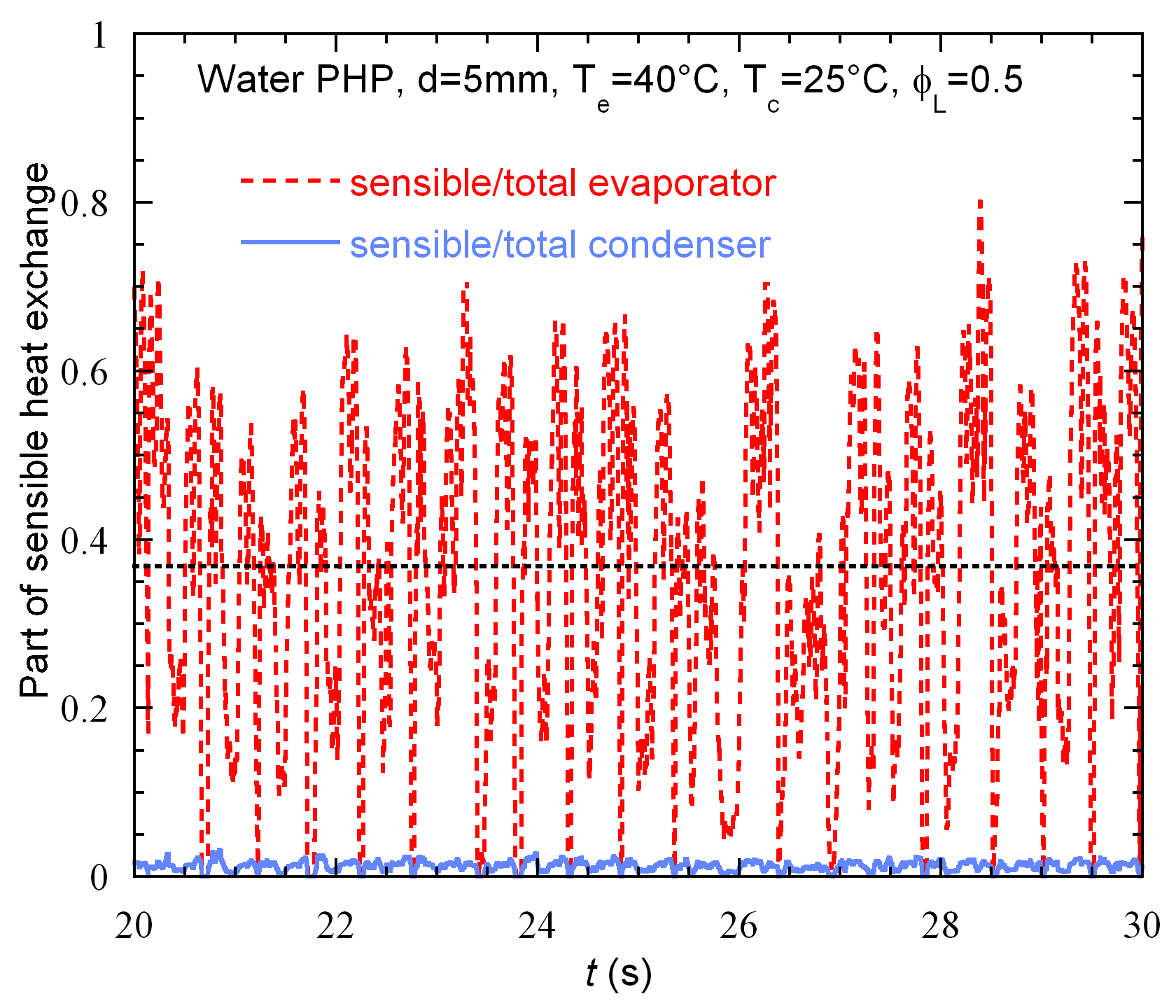
In this particular case, about 60% of the power given to evaporator is transferred as the latent heat due to the film evaporation. The other part of the heat is the convective heat transfer due to heating of colder liquid plugs when they reach the evaporator sections of the tube. Since the condenser sections are most often covered by the liquid plugs, their heated parts located near the menisci penetrate only rarely there. However, during these rare penetrations, the condensation on the films that cover the internal tube walls is quite rapid and is thus much more efficient heat transfer mean than the convective heat exchange. Therefore, a major part (99%) of the condenser heat exchange is performed via condensation, i.e. the latent heat exchange. These theoretical findings were later confirmed by the experimental studies of several research groups.
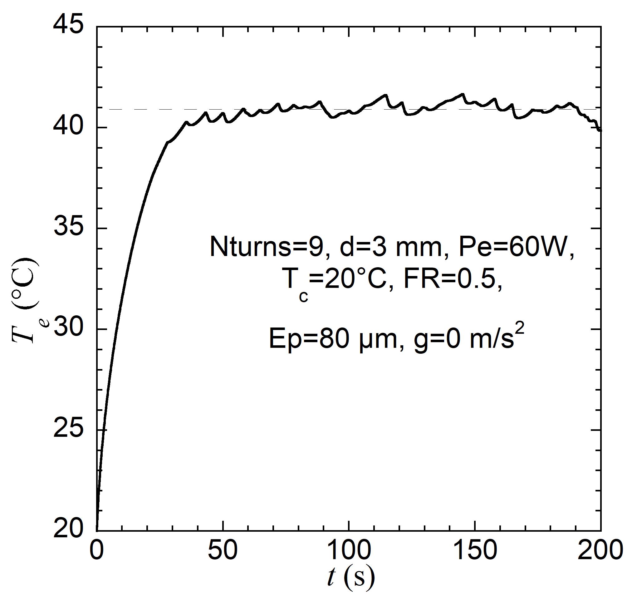
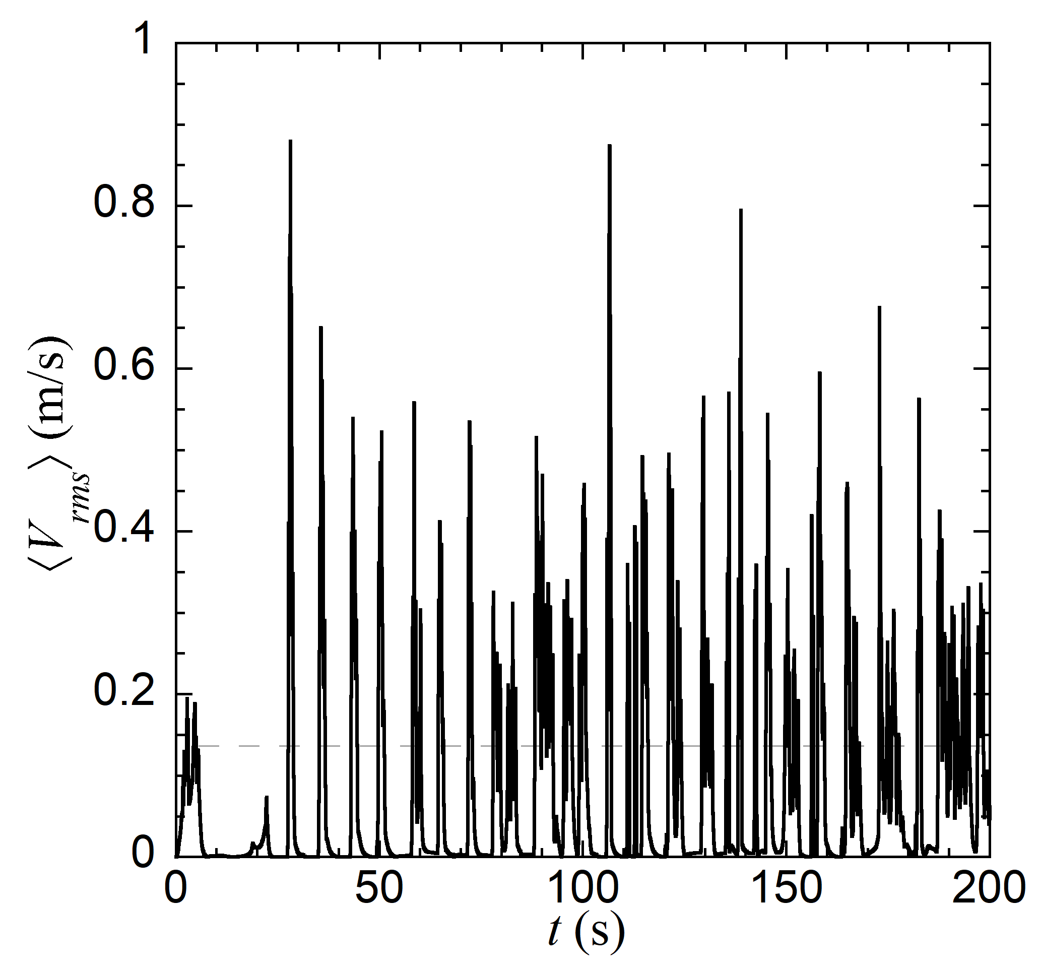
This work concerns the “Space PHP” experiment that will be carried out on board the International Space Station in the Heat Transfer Host apparatus of ESA. The idea of this experiment is to use the tubes of a radius larger than the capillary length on Earth. An example of the simulation performed with CASCO is presented on the pictures below. It is done for a 100 mm long flat plate PHP filled with FC72 that will be mounted on this apparatus. The left figure shows the long time evolution of the evaporator temperature. The right figure shows the corresponding evolution of the liquid plug speed averaged along the PHP.
This project is carried out in collaboration with the research teams from PPRIME institute (Poitiers, France), University of Pisa (Italy), University of Liverpool (UK) and University of Brighton (UK).
For more information, please see this 40 min. video of my lecture on the CASCO code:
Back to the home page of V. Nikolayev
Last change: